3. Microwave Basics
1. About Synthetic Aperture Radar (SAR)
・Sensors Looking at the Earth from Artificial Satellites
Artificial satellites are equipped with sensors that can capture ultraviolet rays, infrared rays and radio waves in addition to visible rays. Therefore, it is possible to see an appearance of the earth that cannot be seen with human eyes. In addition, they are also equipped with radio wave sensors which monitor the rebounding of radio waves emitted by the satellite itself.
One radio wave sensor is the synthetic aperture radar (SAR). Radio waves pass through clouds. Accordingly, it is possible to observe the ground surface even for areas with clouds. Moreover, radio waves are actively emitted and observed. Therefore, we can observe the ground surface whether it is day or not. For that reason, if we make a comparison with an optical sensor for which the captured images depend on the state of the sunlight, it is easier to compare the same point at different times (changes in the morning and at night). This means we can detect those changes.
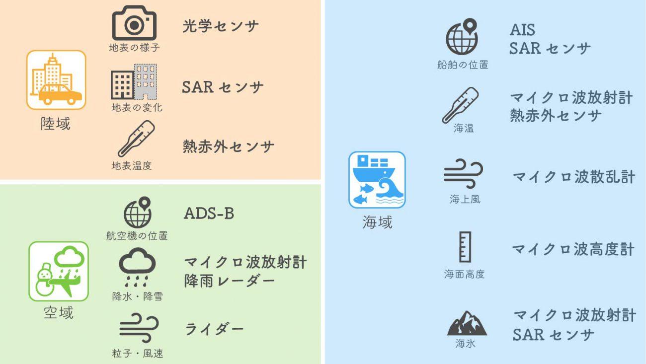
Satellite Sensors and Observation Targets
Credit : sorabatake
・What Is a Synthetic Aperture Radar (SAR)?
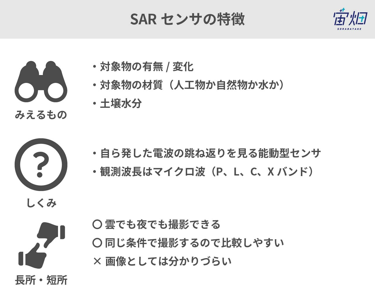
SAR Sensor Features
Credit : sorabatake
SAR refers to synthetic aperture radar. This radar is a sensor that emits microwaves (a type of radio wave) from the sensor and then captures the microwaves that bounce off the ground surface. The “synthetic aperture” refers to the overlapping of the results of the microwaves that have rebounded off the ground surface. This is technology which improves that performance. The rougher the surface, the more radio waves return and the whiter it appears. Smooth surfaces (e.g., water) look black because the radio waves are reflected.
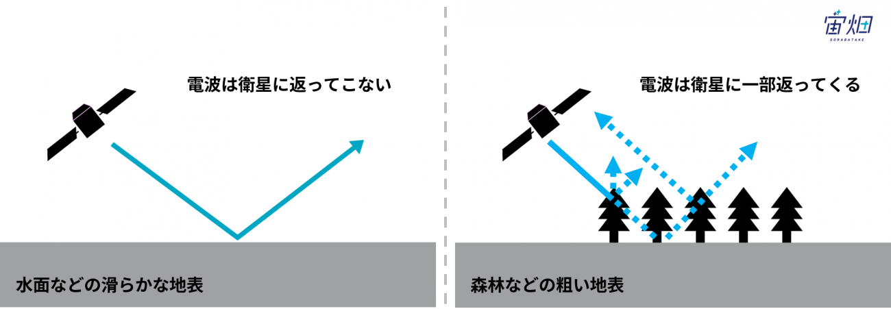
Radio Wave Reflection Method
credit : sorabatake
The images of SAR are not as smooth as those with the sensors of visible light due to the principles of the sensor. Therefore, they are rough images like the ultrasound scans used in the diagnosis of pregnant women.
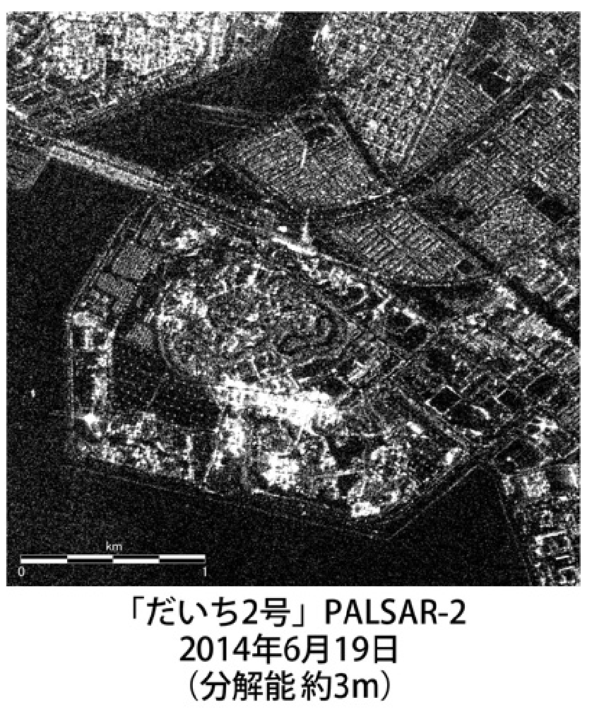
Example of Images Observing the Ground with SAR (Around Tokyo Disney Resort)
Credit : JAXA
・Differences between Ordinary Images (Optical Images) and SAR Images
Differences between Optical Images and SAR Images
Credit : sorabatake
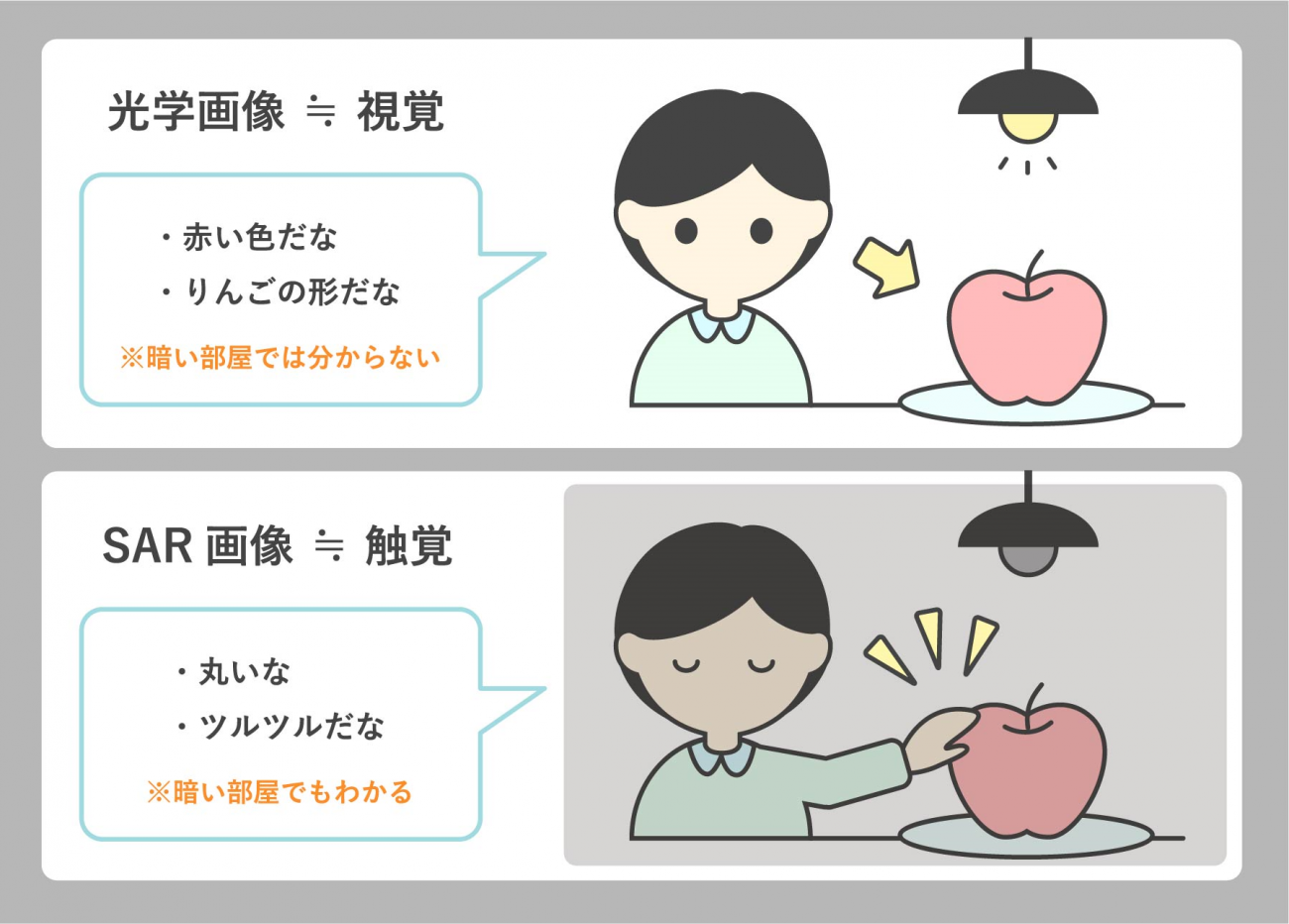
The difference between normal images (professionally called “optical images”) and SAR images is, for example, that optical images are visual information whereas SAR images are tactile information. If you look with your eyes, you can identify the color and shape of the object and what kind of object it is. However, you cannot see anything unless it is bright. Optical images are suitable for identifying the color and shape of objects and the objects themselves. Nevertheless, you cannot see anything at night or when covered by clouds.
On the other hand, we can say that SAR images are close to being tactile information. There is a game on television variety shows in which a contestant is blindfolded and then has to guess what is in a box. This is truly the same. It is possible to find out whether an object is smooth or fluffy and the shape of the object. However, the person touching the object surmises what it actually is based on his or her experience. It observes the rebounding of the radio waves it emits itself. Therefore, the feature of SAR images is that it is always possible to capture them under the same conditions. It is good at detecting changes by visually comparing before/after images compared to optical sensors for which the appearance depends on the state of the sunlight.
SAR Before/After Synthetic Images
Credit : sorabatake
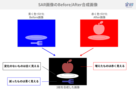
This figure shows the principles of SAR before/after image comparison. If we combine the images by coloring the before image blue and the after image red, we can see the things in only one of the images colored. In this example, the apples are not in the before image, but increase in the after image. Therefore, they are represented in red in the synthesized image. Conversely, the fork in the before image is no longer in the after image. Accordingly, it appears blue in the synthesized image. The dish in both images appears white in the synthesized image. Conversely, the plates that are not found in either image (the parts where radio waves were not returned) look black. In this way, by synthesizing two images captured at different times with blue and red, it is possible to see what has changed at those times.
3.2 SAR Frequency and Things That Can Be Seen
・Observation Frequency
SAR Sensor and Observation Frequency
Credit : sorabatake
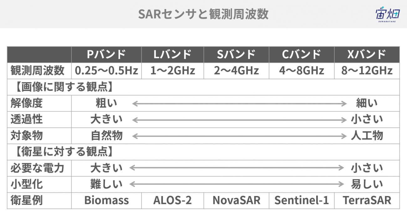
SAR sensors have an observation frequency in the same way as with optical sensors. There are three frequently used frequencies with wavelengths that become shorter in order: L-band (1 to 2 GHz), C-band (4 to 8 GHz) and X-band (8 to 12 GHz). What reflects and rebounds differs depending on the differences in the frequency.
SAR Frequencies and Transparency
Credit : sorabatake
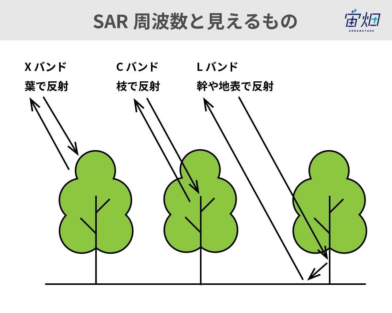
The radio waves pass through tree leaves, branches and grass in the L-band with the longest frequency. Therefore, we can see an appearance close to the trunk and ground surface. This is suitable for observing wide ranging seismic shifts. Radio waves are reflected by the branches in the C-band. The radio waves are reflected by the tree leaves and grass in the X-band with the shortest frequency. Accordingly, this is suitable for looking at finer things in comparison with the L-band or C-band.
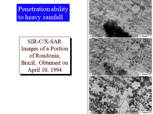
Appearance of a Tropical Rainforest Permeated with Heavy Rainfall due the Difference in the SAR Frequency
Credit : Maurice Douglas
・Polarization
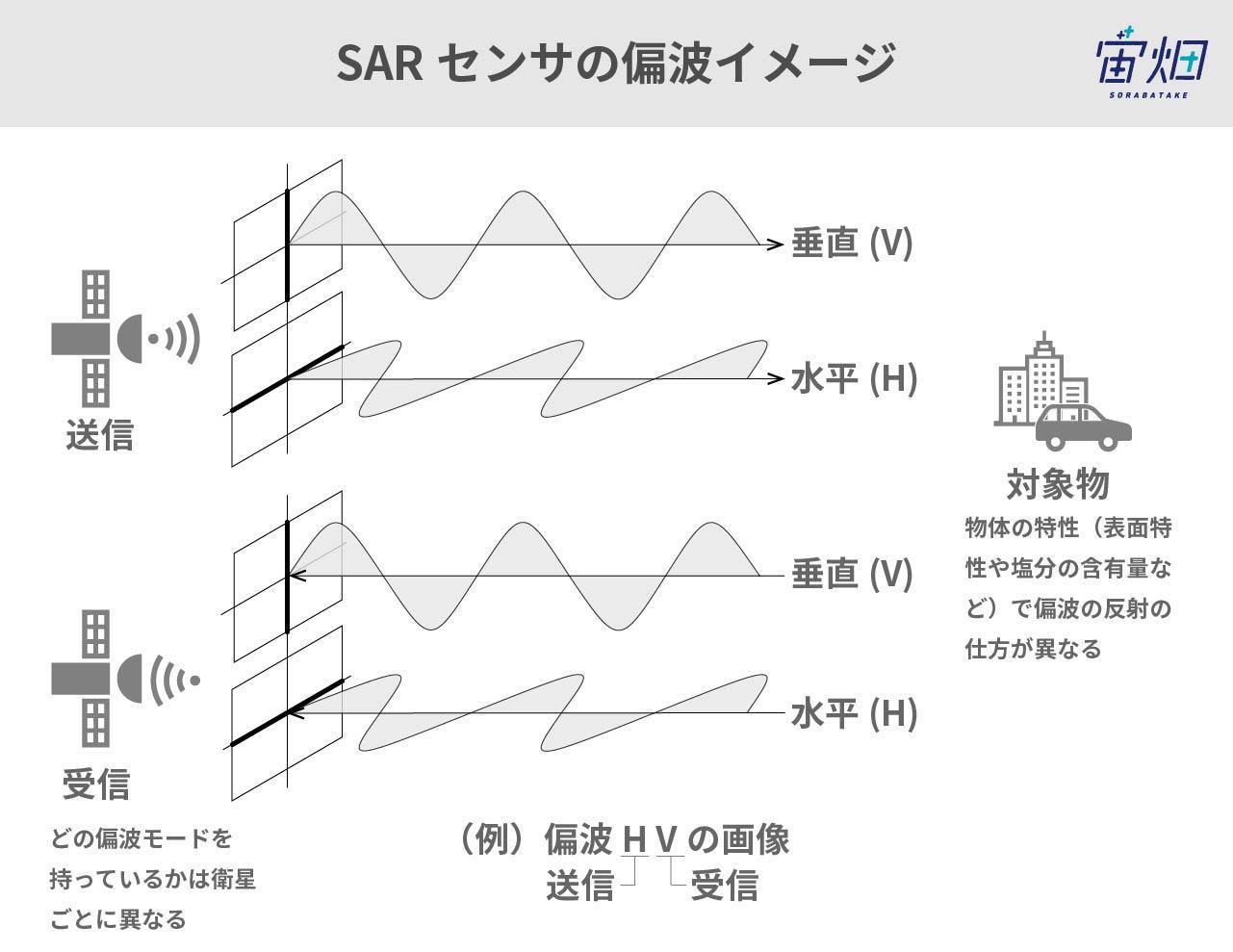
SAR Sensor Polarization Image
Credit : sorabatake
SAR satellites also have a function called polarization. As shown in the figure above, the radio waves of SAR sensors are divided into vertically polarized waves and horizontally polarized waves depending on their vibration direction. Horizontal polarized waves (H) or vertical polarized waves (V) are transmitted. The reflected and returned radio waves are then received horizontally (H) or vertically (V). Transmitting radio waves with horizontal polarization and then receiving them horizontally is called HH while receiving them vertically is called HV. Transmitting radio waves with vertical polarization and then receiving them vertically is called VV while receiving them horizontally is called VH. Some large satellites can receive radio waves both horizontally and vertically at the same time. This is described as HH-HV. This is used for the identification of objects. How the input radio waves are reflected differs depending on the characteristics of the object (e.g., surface characteristics and salt content). Therefore, the intensity of the reflection looks different when turned into an image. For example, it is possible to distinguish between urban areas with many buildings and forests using polarized waves. The waves return without changing direction in places where there are many well-organized surfaces (e.g., buildings). Therefore, the HH/VV signals increase and the HV/VH signals decrease. On the other hand, the waves return in a chaotic direction for surfaces with many irregularities (e.g., forests). Accordingly, the HH/VV signals become weaker while the HV/VH signals become relatively stronger.
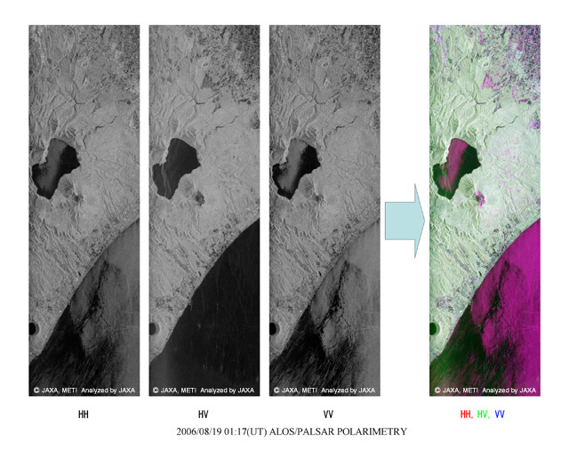
Differences in Images due to Polarized Waves (ALOS/PALSAR)
Credit:METI, JAXA
3.3 SAR Data Processing
・Preprocessing of Satellite Data
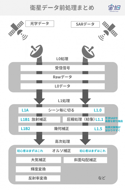
Preprocessing of Satellite Data
Credit : sorabatake
We can roughly divide the processing flow of satellite data into three phases as in the figure: L0 processing → L1 processing → higher order processing. The “L” of L0 stands for “level” and means the processing step. The processing proceeds to a higher order by increasing in level from L1 to L2 and then L3.
The term “standard processing” we hear when handling satellite data is processing officially issued by a satellite data provider. This may be just L1 processing for each data or it may also include higher-order processing.
L0 Processing
L0 processing is the first processing performed when data is received from a satellite. If we look closely at L0 processing, we can see three steps:
(1) Radio waves from satellites are received by antennas on the ground
(2) The received signals are processed for transmission, so are returned to their original signals (raw data)
(3) Unnecessary information is deleted from the raw data (L0 data)
The expression “raw data” is commonly used in the world. However, it is important to note that the “raw data” in satellite data refers to data in this state of (2) and is data that we mostly do not touch.
L0 processing is performed based on the unique design of each satellite. Therefore, it is almost always performed by the company or organization that owns that satellite.
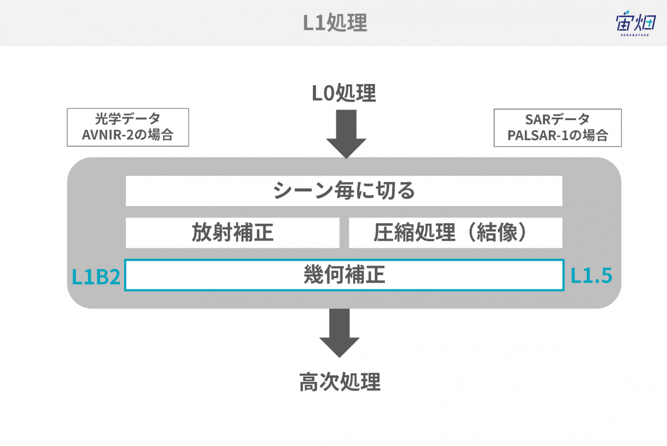
L1 Processing
L1 processing is the basic processing from level 0 to level 1 which is almost all common no matter what sensor is equipped to the satellite. We can broadly divide L1 processing into three stages:
(1) Extraction for each scene
(2) Image sensitivity adjustment / imaging and creation of a picture
(3) Removal of image distortion
These processes are also unique to each satellite. Therefore, they are almost always performed by the company or organization that owns that satellite.
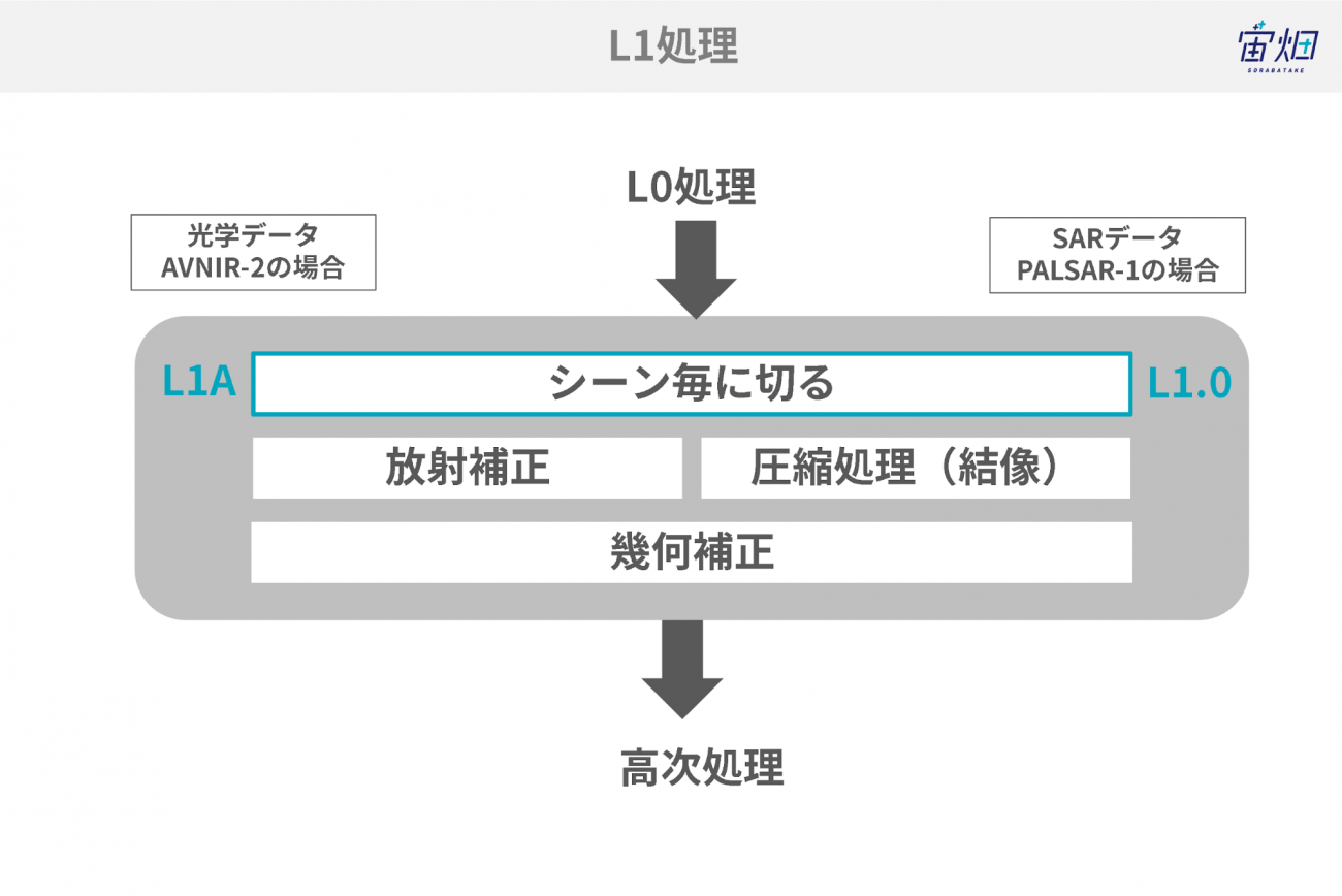
L1 Processing
Credit : sorabatake
In the case of PALSAR-1 of ALOS, we call the processing to cut each scene L1.0. In the case of SAR images, we almost never see data at this level as images. However, these are images that look like sesame with salt.
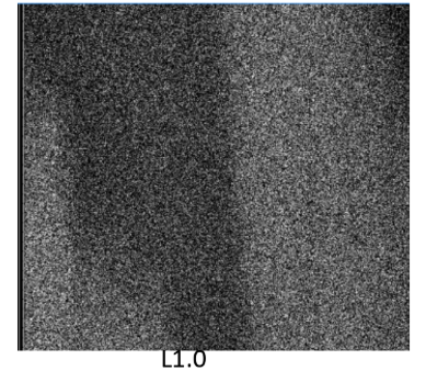
L1.0 of PALSAR-1
Credit :METI, JAXA
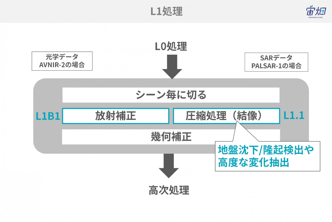
Compression (Imaging) Processing
Credit : sorabatake
The processing performed after cutting the scenes compresses (images) the SAR data. Right angle direction (called the range direction) compression processing and direction of movement (called the azimuth direction) compression processing is performed in the direction of movement of the satellite. With this, the images that looked like sesame with salt up to this point become pictures. This level is called L1.1 in PALSAR-1.
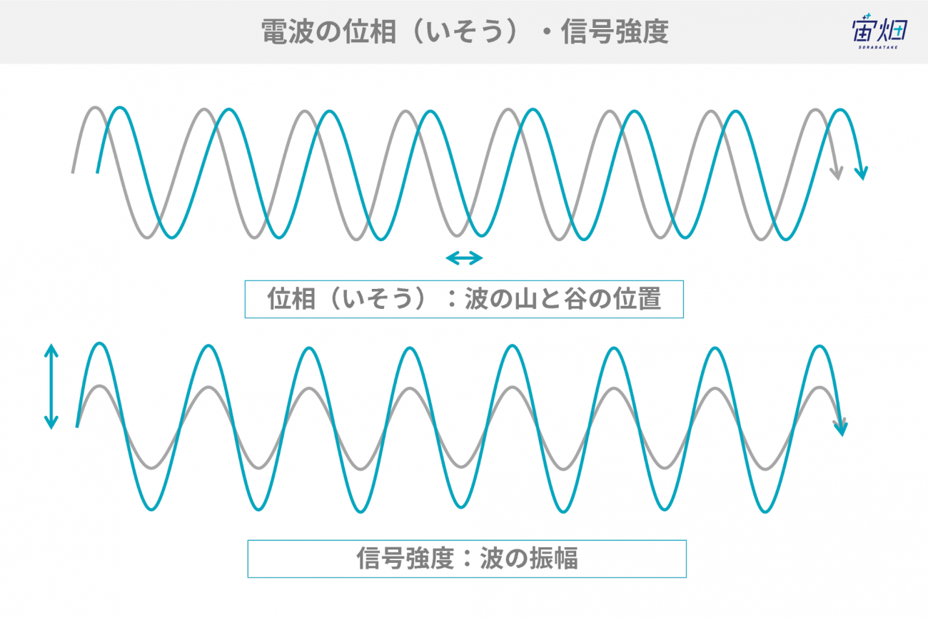
Phase and amplitude of the radio wave
Credit : sorabatake
The L1.1 data contains this phase information, which can be used for analysis such as interference processing and advanced change extraction to identify ground subsidence and uplift.
Geometric Correction (Distortion Correction)
Credit : sorabatake
Processing is performed to reduce noise called multi-look processing in the compressed L1.1. This is processing to equalize to avoid interference with the sesame with salt patterns of images generated due to the coherent nature of radar waves (ease of interference). Overlapping four times is called 4-look processing. However, care is required because if this processing is performed, it will no longer be possible to perform the interference processing that comes later.
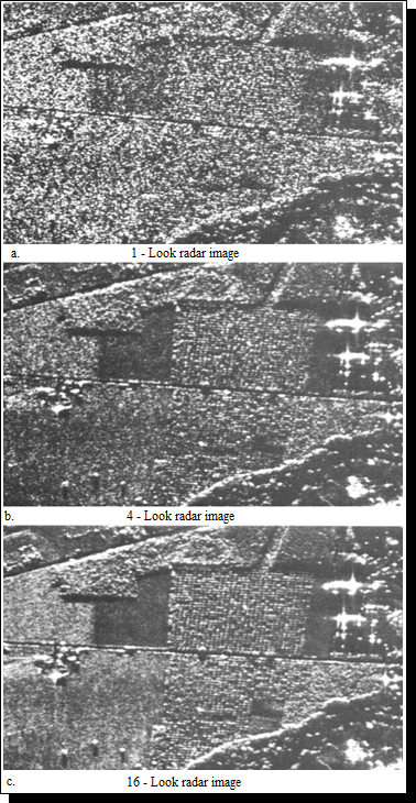
Multi-look Processing
Credit : Maurice Douglas
Furthermore, the map-projected amplitude data is called L1.5. This is data for which the surface objects are easy to see compared with L1.1 data.
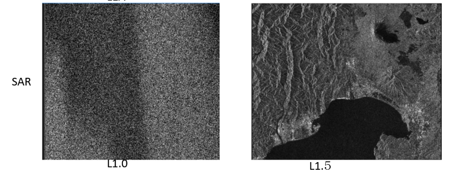
L1.5 Data After Geometric Correction (Distortion Correction)
Credit : JAXA
Higher-order Processing
There is ortho correction processing in one higher-order processing called L2. This is a process in which target objects with a high elevation (e.g., tall buildings and mountains) that appear slanted are restored to look as though from directly above. This results in data that fits perfectly onto maps. This ortho processing is becoming standard for commercial satellites. This means that use in this state is common.
Ortho processing may seem all-powerful. However, it does have one pitfall. It is not possible to see things that cannot be seen. For example, we frequently see sides facing the satellite with the slopes of mountains. The opposite slope is not visible.
One more higher-order processing of SAR data is called slope incline correction. For example, the reflection intensity differs for the slope of a mountain with the slope on the opposite side facing the radar. The appearance of vegetation differs depending on the direction of the slope even in the same cedar forest. Therefore, this is correction in which the effects of slopes are removed based on the terrain data. This correction may be performed when classifying wide areas with a tendency to be mountainous. Slope incline correction is smoother. However, since it is closer to the definition of radar reflection, this is used in the classification of features.
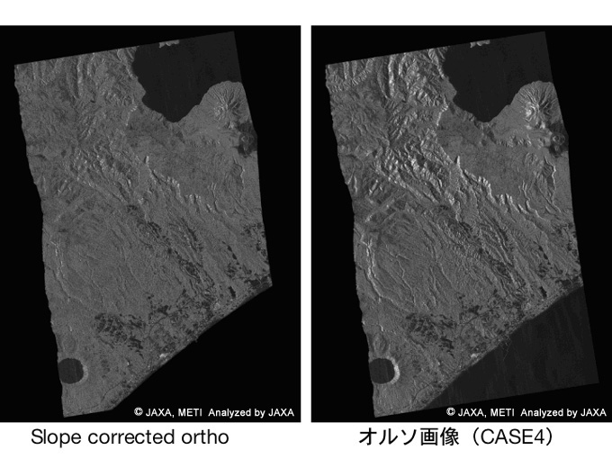
Slope Incline Correction Images and Ortho Correction Images
Credit:METI, JAXA
3.4 Developmental Method of Using SAR Data
・Interference SAR
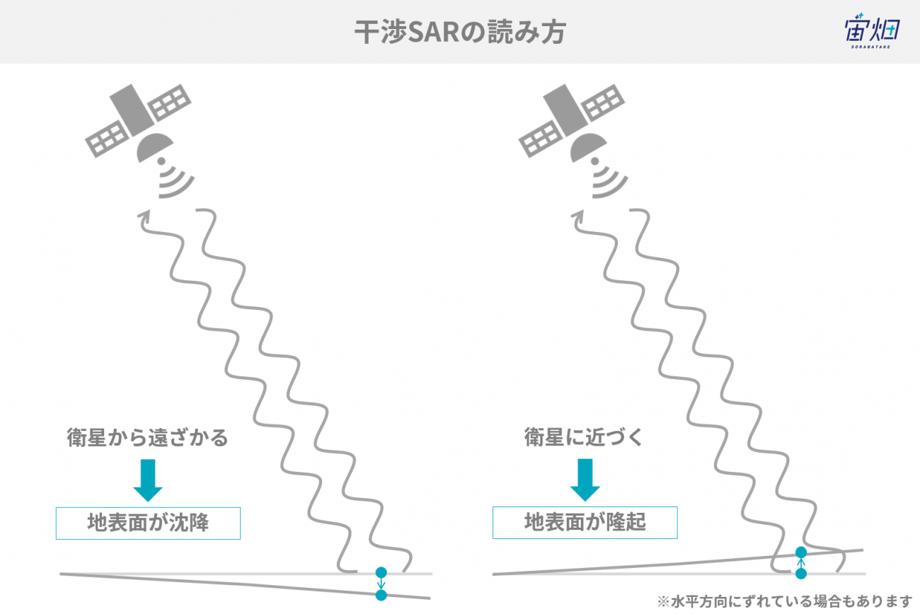
Interference SAR is a technical method of investigating the shapes of the ground surfaces of observation points and their changes by observing the same point multiple times with SAR. Phase contrast information is used to measure the changes in the ground surface with interference SAR.
Principles of Interference SAR
Credit : sorabatake
If there is a deviation between the first observed and the second observed waves (phase contrast), we know that there has been some kind of change (positional shift) on the ground surface of the target. This phase contrast is in the before and after images. If the is a change in the direction in which the distance extends, it is considered that the ground surface has subsided. Conversely, if there is a change in the direction in which the distance shrinks, it is thought that the ground surface has swelled up. For example, the PALSAR-1 and -2 wavelengths are approximately 23 cm. Accordingly, we know that there is a change in the order of about a few centimeters.
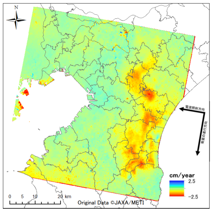
Satellite Utilization Manual in Land Subsidence Observation
Credit: Ministry of the Environment
It is possible to grasp the appearance of land subsidence over a wide area by utilizing this technology. After creating interference images from the satellite different in two different periods, various processes are performed to calculate the difference in the height of the subsidence. There is a possibility noise may be included here due to the impact of water vapor in the atmosphere. Accordingly, multiple calculated results are overlapped to reduce errors (e.g., noise).
・SAR Sharpening
SAR images are black and white. Therefore, it is difficult for humans to determine the features and their changes. Nevertheless, technology to clear up images is being researched by combining optical images and SAR images that have different characteristics. It is possible to create images with even more information by combining two types of image.
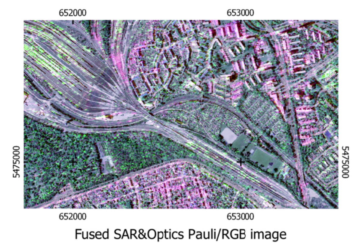
SAR Sharpening
Credit : A. Schmitt and A. Wendleder 2018. CC BY 4.0 License
・SAR画像のカラー化
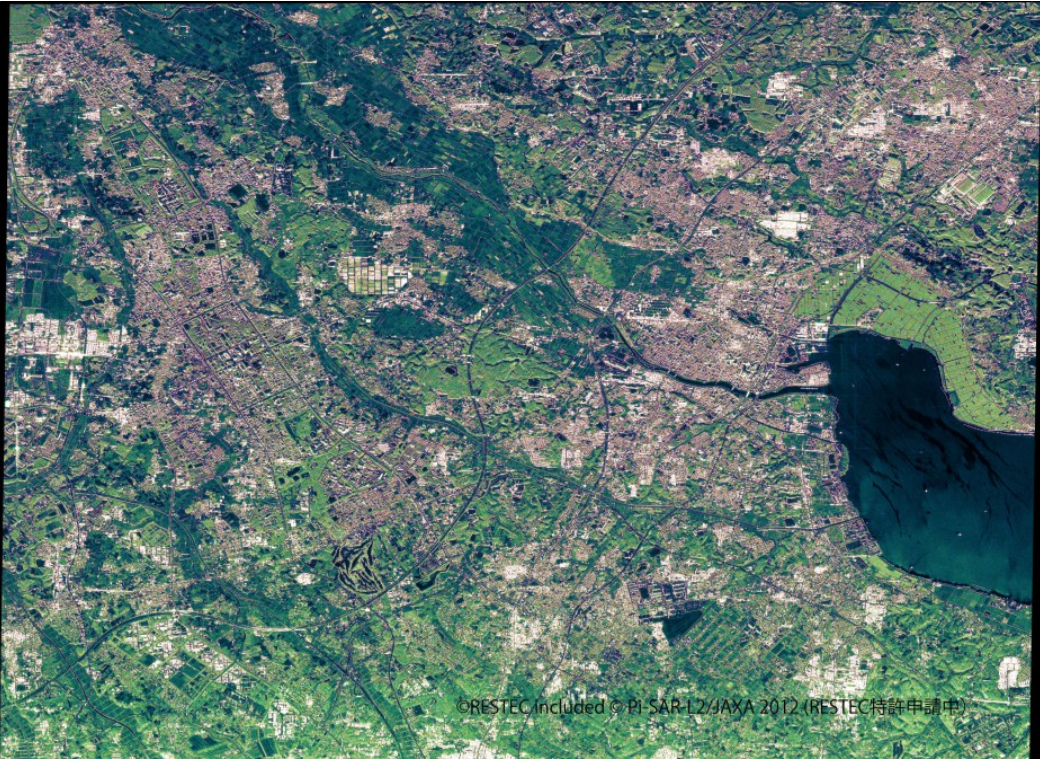
Colorized Images Based on Aircraft SAR (Pi-SAR-L2) Images
Credit : RESTEC
Attempts have been made to give color like optical images to SAR images that are difficult to understand because they are in black and white. Objects are automatically surmised (this is a forest or this is water) and then colored from the surface properties (e.g., smooth or rough) obtained from SAR images.
【Reference Materials】
1. Active and Passive Microwave Remote Sensing Lecture 7 Oct 6, 2004 Reading materials: Chapter 9.
2. PALSARによる偏波観測
3. 地盤沈下観測等における衛星活用マニュアル
4. SAR-Sharpened Image of Kuwait, Iraq and Iran – June 18th, 2011 SAR-SHARPENING IN THE KENNAUGH FRAMEWORK APPLIED TO THE FUSION OF MULTI-MODAL SAR AND OPTICAL IMAGES
5. ~世界初!だいちを彩る新技術 SAR画像をより身近に~ 陸域観測技術衛星2号「だいち2号」(ALOS-2)搭載LバンドSAR画像のカラー化技術について